The Fine Things are Always Hand Made
Restoring My Scott SLRM
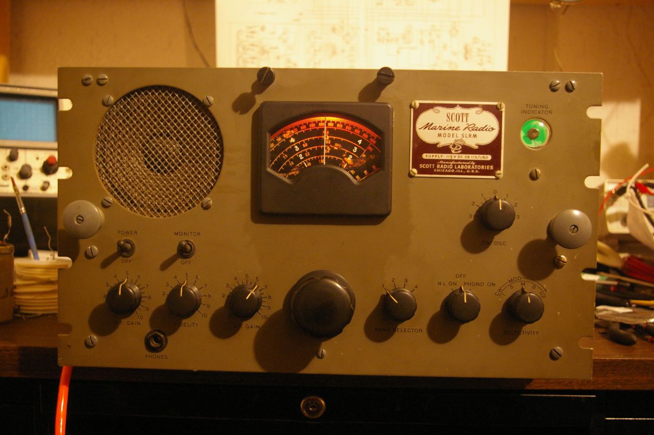
About a year ago I bought a Scott SLRM off eBay. I got it for a very good price. The shipping cost more than half what the price of the radio itself came to ! Yup, this thing is HEAVY. This thread will document my restoration of the receiver. First some shots of the radio as I received it.
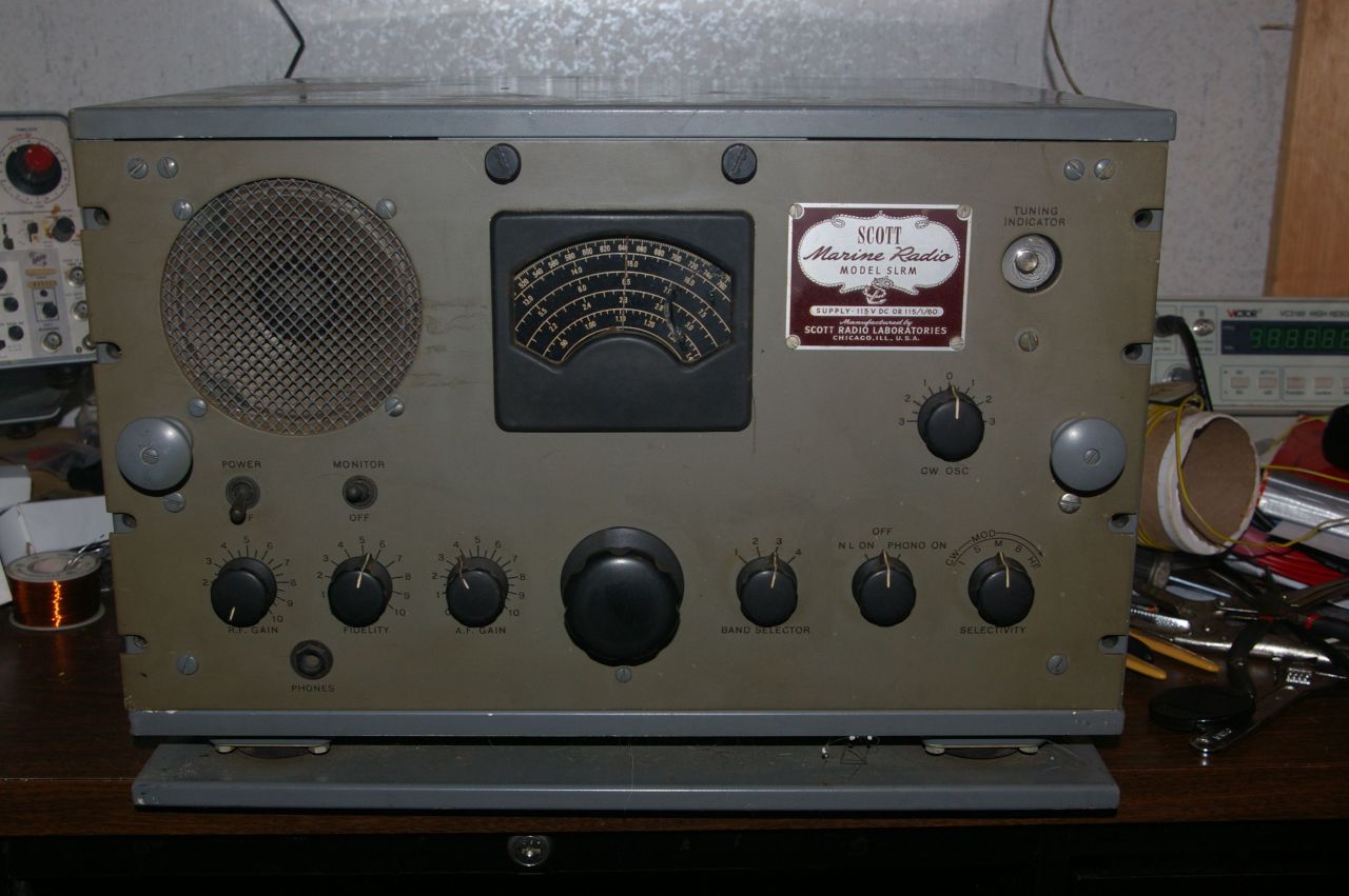
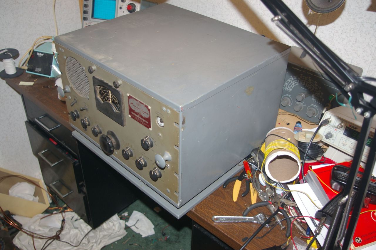
She was not in too bad condition when she arrived. The plastic dial glass was gone, and the power cord was an 18 gauge piece of junk that looked like it came from a 1950s lamp, but otherwise the radio was in nice shape. Happily it came with the correct power inlet and mating connector, so replacing the power cord will be a breeze. Sadly, the radio is missing the special connector that plugs into the antenna jack. Once the external assessment was done, I went on to removing the chassis from the heavy steel cabinet in which it arrived.
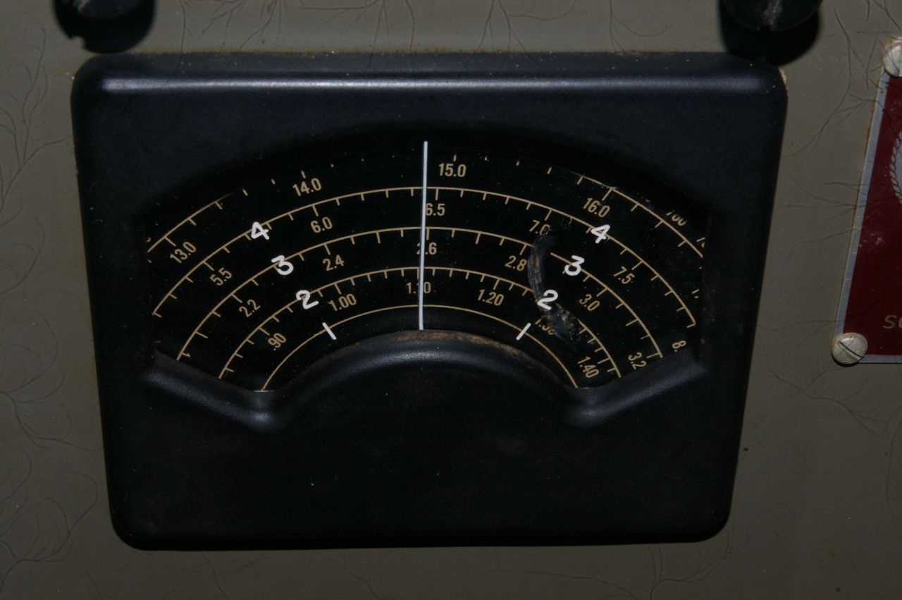
The first work I did was replace the plastic dial glass. Happily Robert F, from this site, a friend of mine from Philco Phorum, sent me one he had extra which Mike H from this site had made for him. Replacing the dial cover was not an easy task. It required removing the entire front panel of the radio. First I removed the knobs. These are SERIOUS knobs with two set screws each ! Then there were 8 screws with nuts and lock washers, and one smaller screw holding the front panel to the chassis. Two of the screws with lock washers are real bears to remove since the nuts and lock washers are buried and almost impossible to handle while turning the screw. All the others are fairly straightforward. The smaller screw goes into a standoff and was the simplest of all to remove. Happily none of the jacks or other attachments to the front panel need to be removed. There is enough free length of wire attached to them. Once the panel was off, I removed the bezel for the dial glass from the panel. It is held by 4 small screws. I then removed the dial pointer from the inside of the bezel. It is held in place by a single little screw. Behind the pointer, between it and the bezel body, I found some remains of the original plastic dial glass, all shriveled and brown. There were a few little remains of it also around 4 little brass studs around the edges of the bezel inside which help align the dial glass. I took the new dial glass and began to fit it. I had to drill the 4 holes to go over the studs, and sand the edges of the piece to just fit inside the slight recess for it in the back of the bezel. I sanded the dial pointer smooth, removing the old flaking paint on it, and repainted it white. When it was dry, I fitted the new dial glass into the bezel, and set back the dial pointer to retain it along with its little screw. This is what it looks like all finished...
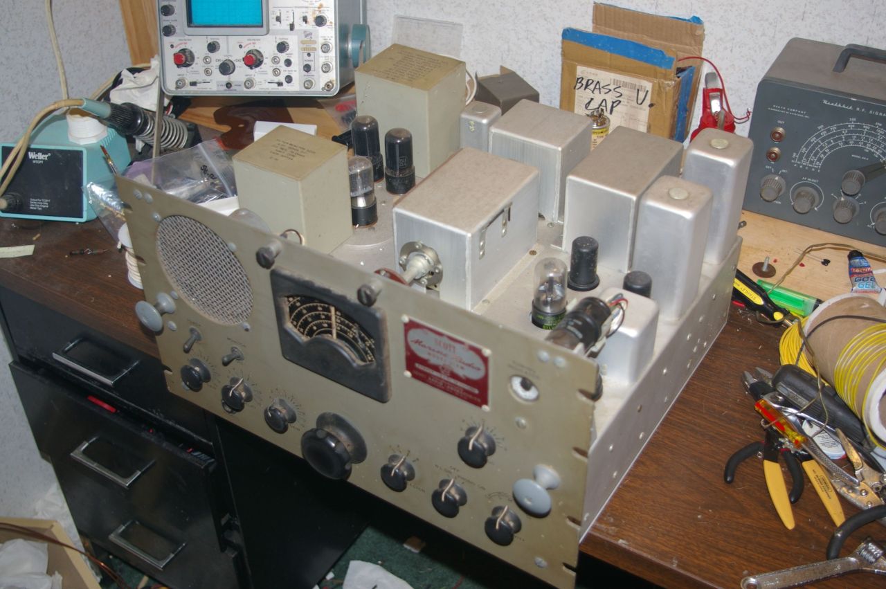
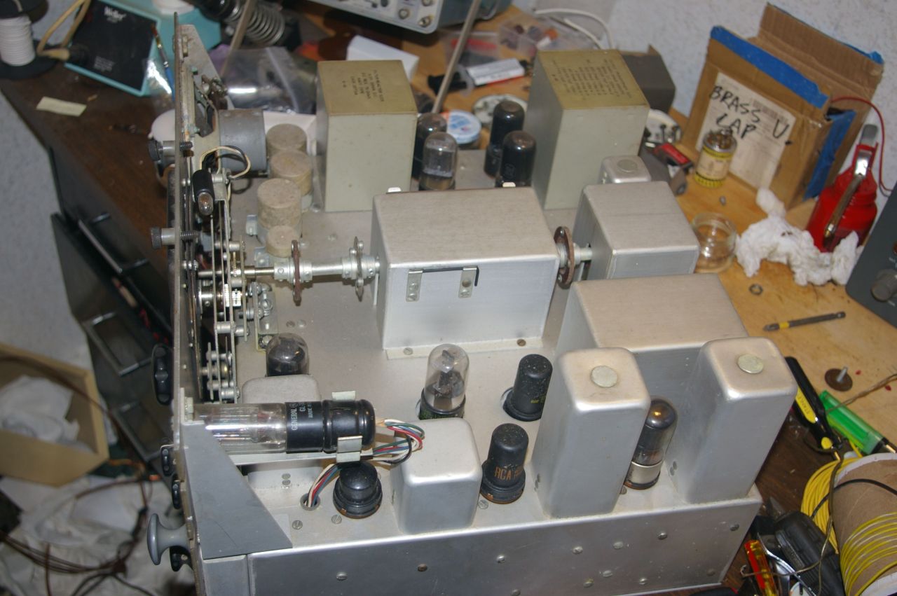
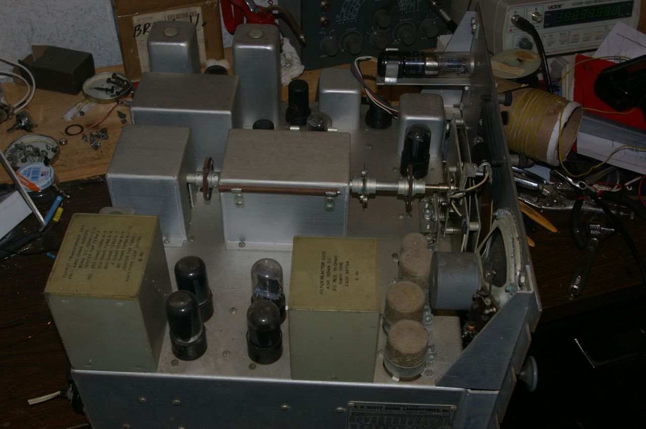
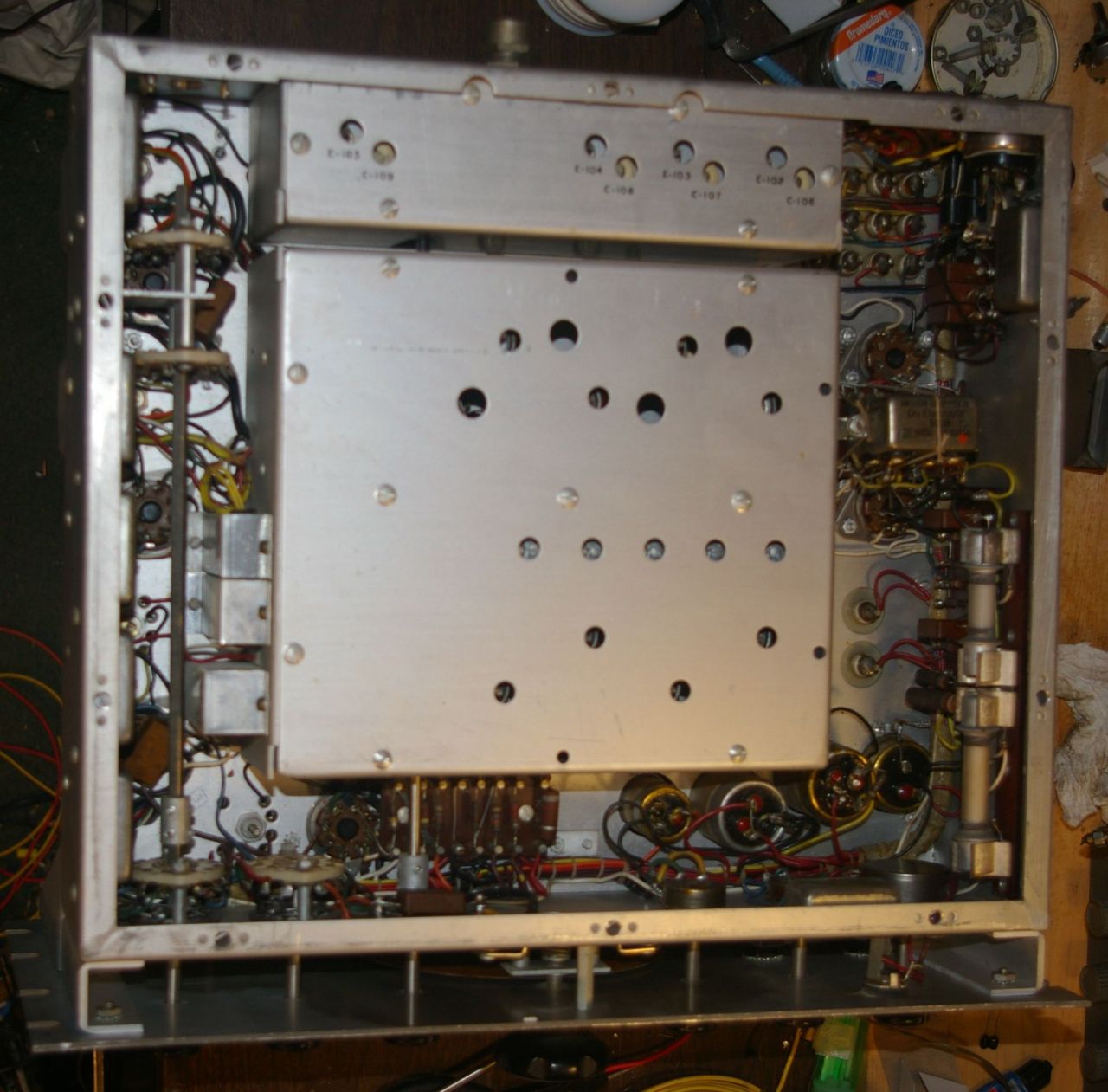
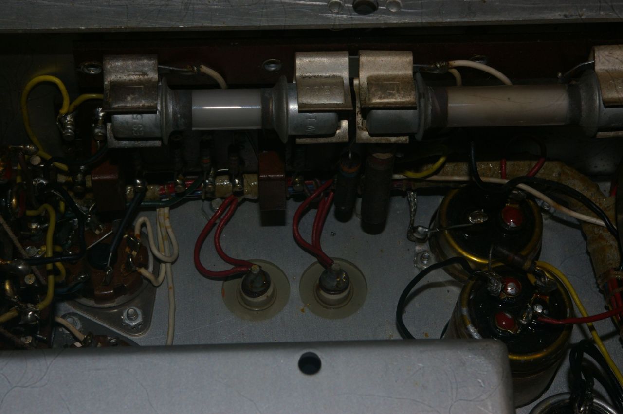
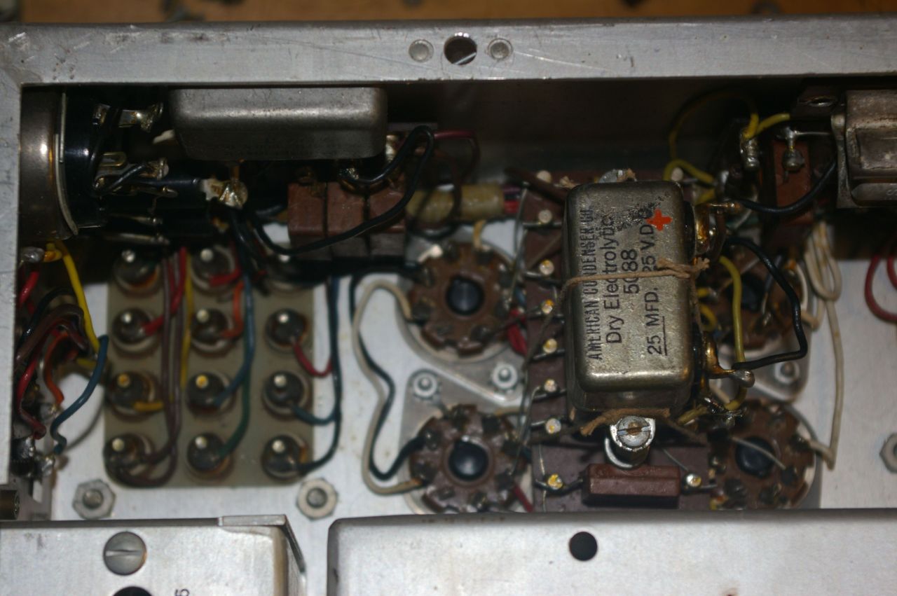
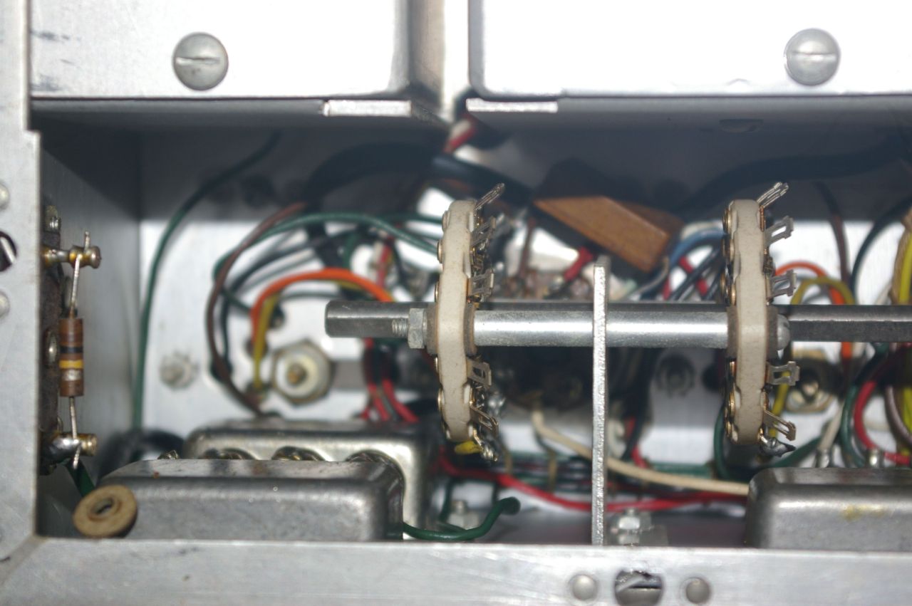
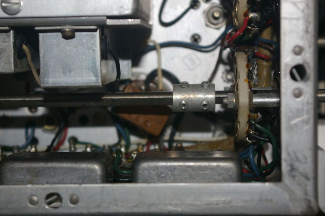
After that I removed the bottom plate of the chassis, and began my assessment of the radio. I was very happily impressed. I have never seen such a beautifully, and durably built radio since my Navy days. This radio was SERIOUSLY constructed to weather the elements at sea. I have decided to take Robert F's lead and start by just replacing the electrolytics. I will probably measure them and take good pictures of them, and see if Hayseed Hamfest can make me some replicas to use. All the paper condensers one would normally have to replace are hermetically sealed away from the elements in oil filled little metal cans, so they may well be fine for years and years. Here are pictures of the underside of the chassis before I start any work. First is an overall view, then a series of shots going from the electrolytics down that side of the chassis, then up the other side to the front, and finally the middle of the front.
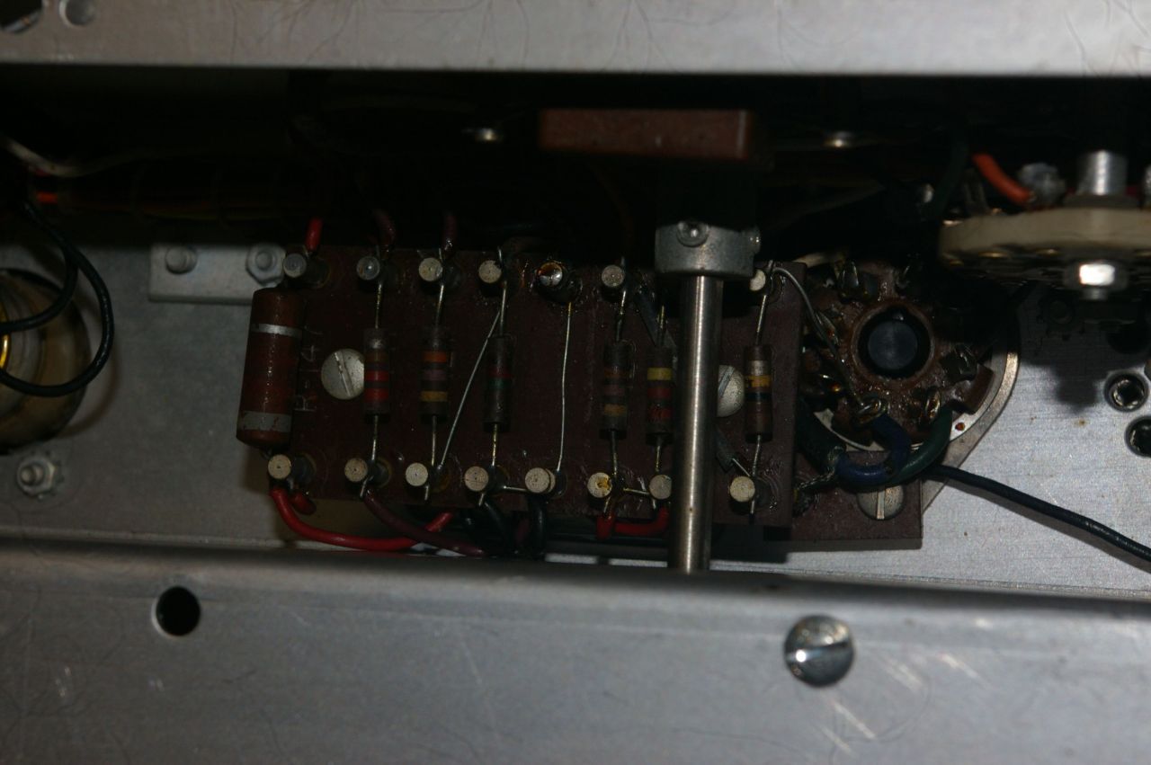 So, that is all the progress so far. I have ordered some parts and am waiting for them to come in. I have also contacted Hayseed Hamfest to see if they can make me custom replacements for the 4 electrolytic condensers along the front of the receiver. I have bought a full set of replacement condensers from them for restoring my National SW-54, and NC-125 radios. They made PERFECT replacements for the 4 wire firecracker in the SW-54, and the can in the NC-125. Fortunately, the parts list in the manual for the SLRM gives quite exact specs for these condensers, with the diameter, length, number of terminals, and so on, which I passed along as well as a JPG of the schematic. I hope they can make the new condensers for me. Stay tuned for more of this continuing adventure.
Replies to This Discussion
-
Permalink Reply by Michael Lawton on
-
Today the 4 condensers I ordered from Hayseed Hamfest finally arrived. They were mailed on the 16th. There was a tracking number, but after it left their local post office there were no more scans of it along the way until it arrived today, then other scans magically appeared. I think the USPS was playing CYA.
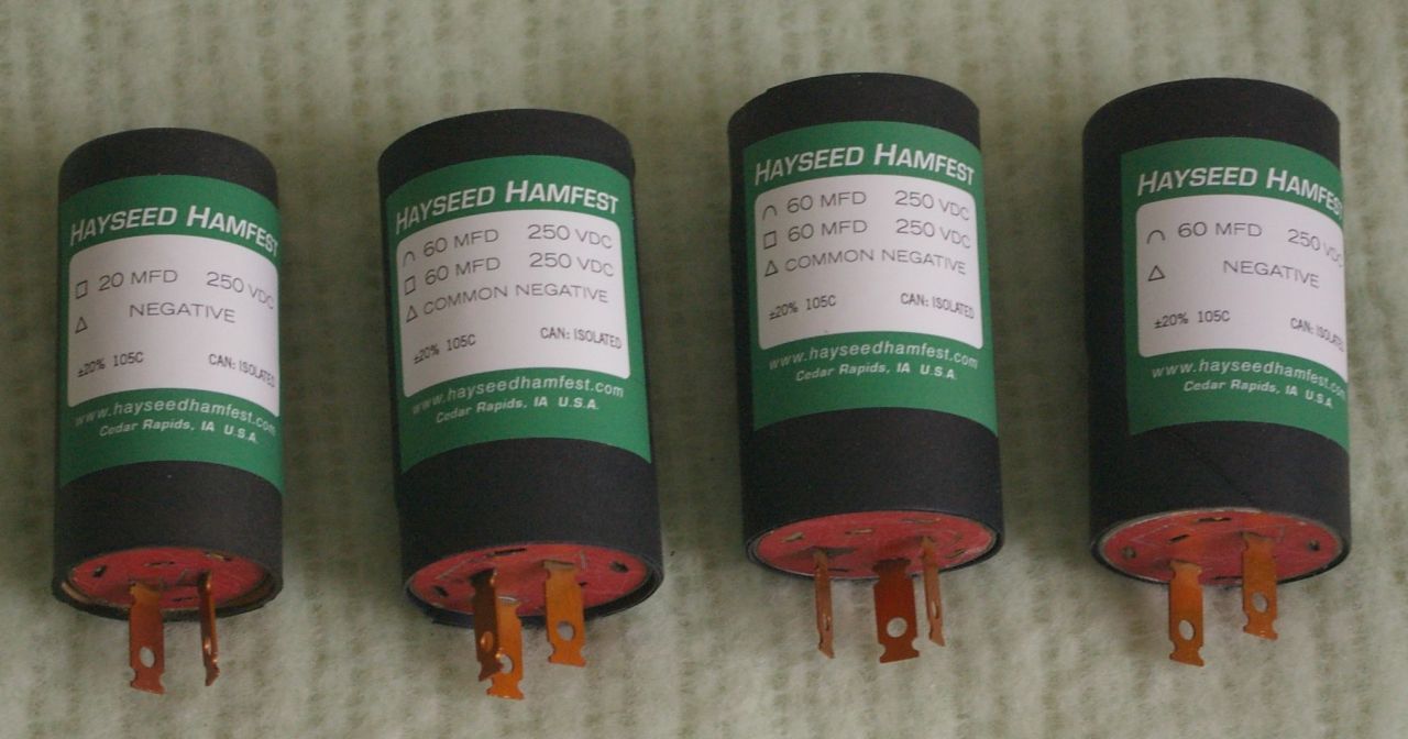
I had to go to Morristown today for my eye treatment for macular degeneration. When I got back I began to replace the original electrolytic condenser cans. Much to my chagrin I found that the ones from Hayseed Hamfest were just a HAIR too big to fit through the hole in the chassis, and three of the four barely fit into the original clamp, the fourth didn't fit at all. I checked the specifications I sent them, which were exactly what is listed in the bill of materials in the Scott manual. They made them with a diameter just a little too big. The original spec for the three was 1 3/8" diameter, in other words 1.375", these were between 1.450 and 1.5" Fortunately I was able to fit these into the original clamp, with the clamping screw hanging on by about 3 threads, and keeping them raised a hair from the chassis top was able to use them. The terminals cleared OK. The fourth one was similarly over the specified size, but was so much bigger that it could not fit in the clamp, so I didn't use it. Instead I mounted a 20MFD 450V condenser on a 3 terminal strip, and screwed it under the chassis using one of the original screws that held the clamp.
Once all the condensers were installed there was nothing left to do but try the radio out. I hooked it up, and it works very well. I am able to pick up a LOT of stations on just my test antenna at my workbench. I still have a little more to do, clean the band switch contacts and other contacts but the radio actually works very well. So, here are pictures of today's work...
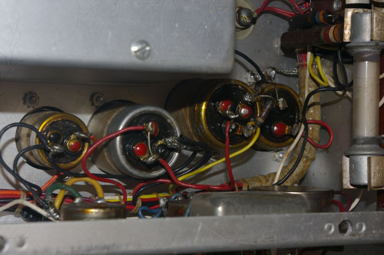
First, the four condenser cans before installation...

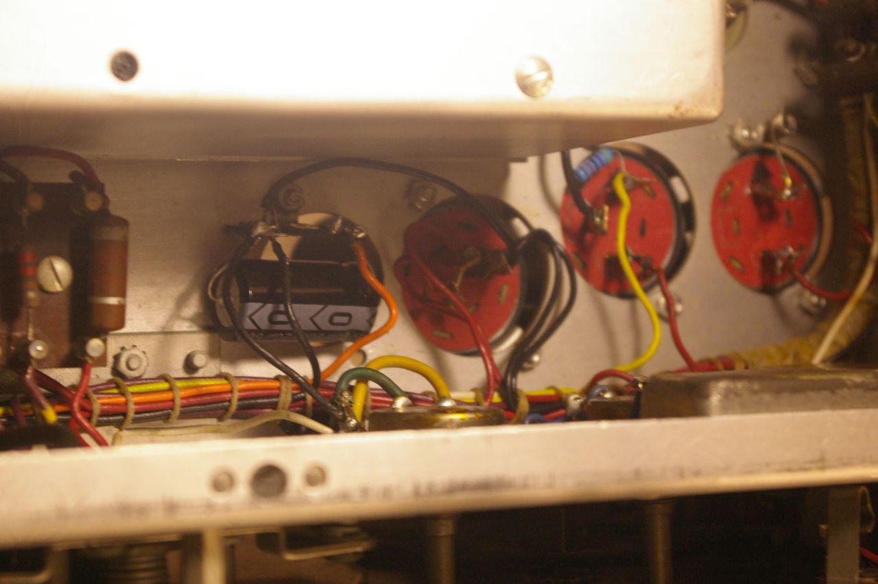
The new electrolytic condensers installed, under chassis view...

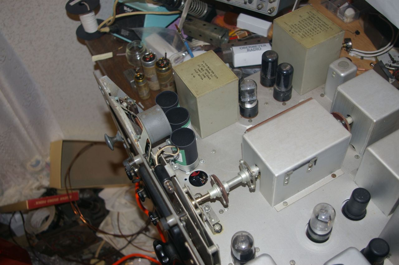
The new condensers installed top of chassis view...

My Scott SLRM playing on my workbench...

-
-
Just a quick update tonight. I sprayed all the switch contacts and worked them back and forth a lot last night, then let them sit and dry. Tonight the radio really came alive and is working very well. So far I have just used my 10 feet of wire strung up around my work bench as a test antenna. As you read above, I replaced the special old style U.S. Navy antenna connector with a modern SO-239. I am just using it as a connector, NOT with coax and a balanced feed line. So far I am just using the center post of the PL-259 to connect the antenna. I will make a small label explaining the situation and affix it to the back of the chassis beside the plug after I put the radio back in its steel cabinet. With just that antenna I was able to pick up stations all over the standard broadcast AM dial, WSM in Nashville comes in very clear, as do stations WRVA Richmond, VA, and WLW from Cincinnati, OH, just to name a few of MANY. The reception rivals any of the "communications receivers" I have recently refurbished. I did not do any alignment at all, just replaced the input "death caps" and the filter electrolytics, and changed the antenna connector. On the next band up I was able to get CHU Canada at 3.33 MC clearly as well as the top of the AM broadcast band below that, and some shortwave stations above it. Between there are Ham bands and I get a lot of RF hash from the high tension lines at those frequencies. On the next band I was able to get WWV at 5 MC, which I almost NEVER pick up with that wimpy indoor antenna, but it came in very intelligibly with moderate fading. On the highest band I was able to receive WWV at 10 MC as well as several shortwave stations. I can't imagine what it will do hooked to my outdoor antenna! From what I have seen so far, this receiver rivals or excels the National NC-125, and the Lafayette HE-30, which is a pretty tall order. I haven't tried out the CWO on the ham bands yet. I'll wait until I connect it to a better antenna, but that should be pretty interesting too. If it is at all like the National or Lafayette it will take some playing with to master that.
-
Permalink Reply by Ken Carr on
-
I appreciate your description of how you prepared the Scott SLRM. I just purchased one last weekend while at the New England Vintage Electronics fleamarket. It is a hefty 55 pounds. Mine is in excellent cosmetic condition and someone had already replaced the old antenna connector with an SO239. They had also replaced the cord connector with a modern 3-conductor computer power cable connector. I tried to power it up with an inline light bulb and variable transformer attached. This setup promptly tripped my GFCI outlet. Skipping the variac and bulb gave the same results. Finally I powered it up with an isolation transformer attached and it worked perfectly. My next job will be to open it and check to see if the power cord is properly wired as you mentioned with terminals 1,2, and 3.
Please feel free to post any updates on your radio that you may have. These are quality receivers, exactly as expected from Scott.I have attached some photos of my ‘new’ radio.
- Attachments:

-
Permalink Reply by Scott Seickel on
-
That looks like a nice clean unit Ken. Good luck with it.
Ken Carr said:I appreciate your description of how you prepared the Scott SLRM. I just purchased one last weekend while at the New England Vintage Electronics fleamarket. It is a hefty 55 pounds. Mine is in excellent cosmetic condition and someone had already replaced the old antenna connector with an SO239. They had also replaced the cord connector with a modern 3-conductor computer power cable connector. I tried to power it up with an inline light bulb and variable transformer attached. This setup promptly tripped my GFCI outlet. Skipping the variac and bulb gave the same results. Finally I powered it up with an isolation transformer attached and it worked perfectly. My next job will be to open it and check to see if the power cord is properly wired as you mentioned with terminals 1,2, and 3.
Please feel free to post any updates on your radio that you may have. These are quality receivers, exactly as expected from Scott.I have attached some photos of my ‘new’ radio.
-
-
Thanks, Scott. The radio looks new inside and out! I made a reasonable offer to the owner and then we just “talked radio” for some time after which he said “You can have it for what you offered.” I meet the best people in the radio hobby!
Scott Seickel said:That looks like a nice clean unit Ken. Good luck with it.
Ken Carr said:I appreciate your description of how you prepared the Scott SLRM. I just purchased one last weekend while at the New England Vintage Electronics fleamarket. It is a hefty 55 pounds. Mine is in excellent cosmetic condition and someone had already replaced the old antenna connector with an SO239. They had also replaced the cord connector with a modern 3-conductor computer power cable connector. I tried to power it up with an inline light bulb and variable transformer attached. This setup promptly tripped my GFCI outlet. Skipping the variac and bulb gave the same results. Finally I powered it up with an isolation transformer attached and it worked perfectly. My next job will be to open it and check to see if the power cord is properly wired as you mentioned with terminals 1,2, and 3.
Please feel free to post any updates on your radio that you may have. These are quality receivers, exactly as expected from Scott.I have attached some photos of my ‘new’ radio.
-
-
WOW, Ken, that is a real beauty ! In better cosmetic condition even than mine. Mine was missing those side trim rails with the screws. So check the wiring of the power socket. I was fortunate that mine came with the original socket and also with the original connector for that socket. All I had to do was replace the line cord.
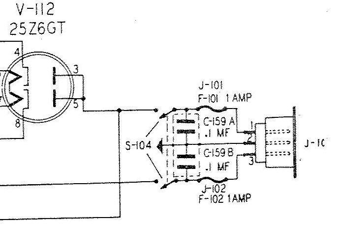 The only condensers I replaced, besides the power electrolytics, were C159A and C159B. I used modern safety caps of the same value. You may wish to do the same.

-
Permalink Reply by Norman S Braithwaite on
-
C-159A & B should be replaced with 0.01-mfd capacitors. They are perfectly adequate for the application and the 0.1-mfd capacitors will pass enough AC current to trip GFCIs.
Norman
-
-
I will surely replace those capacitors! Thanks for the advice. Currently working on an RCA 143 that I must complete first. Then I’ll update the Scott.
Michael Lawton said:WOW, Ken, that is a real beauty ! In better cosmetic condition even than mine. Mine was missing those side trim rails with the screws. So check the wiring of the power socket. I was fortunate that mine came with the original socket and also with the original connector for that socket. All I had to do was replace the line cord.
The only condensers I replaced, besides the power electrolytics, were C159A and C159B. I used modern safety caps of the same value. You may wish to do the same.
-
-
Thanks, Norman. That makes a lot of sense that they are the root of the shutdowns. Another radio person on Facebook also told me that these caps are the likely source of the problem. I will also rewire the plug since it appears backwards to me (please see my previous separate post a out that).
Norman S Braithwaite said:C-159A & B should be replaced with 0.01-mfd capacitors. They are perfectly adequate for the application and the 0.1-mfd capacitors will pass enough AC current to trip GFCIs.
Norman
-
-
I built a special antenna so that I could mount it on my front porch and run the lead into my bedroom where I have the SLRM. I did use it connected to the antenna in my back yard beside my back porch right after I finished working on it, and it received about as well as my National NC-125.
Instead of just an open wire from the antenna to the SLRM, I decided to use a shielded cable this time to try to shield out some of the noise that come from the TVA 160,000 volt power lines that run across my pasture about 150 feet from this new antenna. they are even closer to the on beside my back porch, which is why I have designed these special vertically oriented antennas, but that is another story. On the base of the new antenna I mounted an SO-239 connector with the center connected to the antenna wire itself....

When all done, and I tested the radio with the antenna the performance was, er... , underwhelming. I checked the antenna... no short between the center conductor and the shield... I tested the tubes... they were all good. I wracked my brain and tried lots of different things. with the center pin inserted into the receiver's SAP-239 connector, but the rest of the PL-259 out a little so the shield was not touching, and so not grounding to the chassis of the SLRM, performance improved. Finally, I tried just connecting the shield and center conductor together, isolated from the outer part of the PL-259, and performance was much better. I did the same on the other end where the cable connects to the antenna, so basically it is now just a single, unshielded conductor going from the antenna wire to the antenna input at the center connection of the SO-239 on the back of the receiver. It is working as well as it has so far with this antenna. Day times here are pretty rough for reception, so I can hardly wait until tonight to really see how much things have improved.

-
-
Well, indeed the radio performed better tonight, I got more stations across the AM broadcast band including WSM 650 KC in Nashville. I was able to receive WWV on both 5 and 10 MC. WRMI 5.95 MC from FL came in very strong, and there were many stations to be heard on band 3 and 4. I was disappointed not to hear CHU on 3.33 MC.I think I am going to rebuild the antenna, increasing the height of the top mast section, and reducing the number of turns in the loading coil between the two mounting pieces. We'll see how that goes.
-
-
Thinking about what I did to this receiver when I got it up and running, it occurred to me that I had NEVER CLEANED THE BAND SWITCH SECTIONS ! Heck, I never even opened up the center section of the underside where the switch and associated coils lurk ! All I have done is replace the four power supply electrolytic condensers and the two on the power input. So today I sprayed the dickens out of the band switch segments with Deoxit, and let the radio dry until tonight. WOW ! What a difference on the AM broadcast band. The shortwave bands were better too, but it was the AM broadcast band where the difference was most noticeable. The radio is back to the way I remember it working when I first had it on my bench so long ago. I still think, with a bit higher antenna I will have even better reception. Here in the mountains, the hills play games with RF signals. An antenna height that may be sufficient in one place, in another, more masked by the hillside, that same height may not be sufficient. I can get CHU on 3.33MC with my HQ-129-X on the similar antenna on the back of my house, farther away from the mountainside. I want to be able to hear it on the Scott with the antenna on the front. That will be my next project, rebuilding what I just finished... LOL.
- ‹ Previous
- 1
- 2
- 3
- Next ›
© 2026 Created by Kent King.
Powered by
![]()