The Fine Things are Always Hand Made
Hi all! So I'm the proud owner of an Allwave Deluxe that I picked up at the NWVRS swap meet last weekend near Portland, OR.
I'm not new to restoring antique radios - but this is my first EH Scott. I'm sure I have a ton to learn about these radios and it sure looks like I've found the right people to learn from!
So first things first - the serial number is U 226:
Cabinet
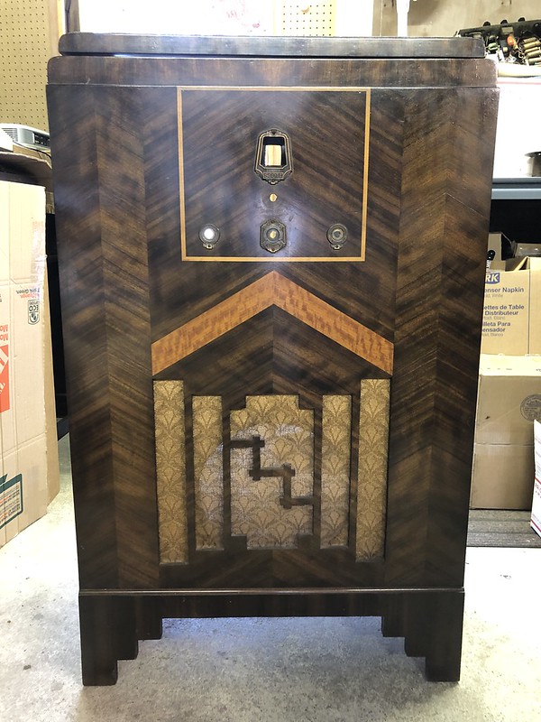
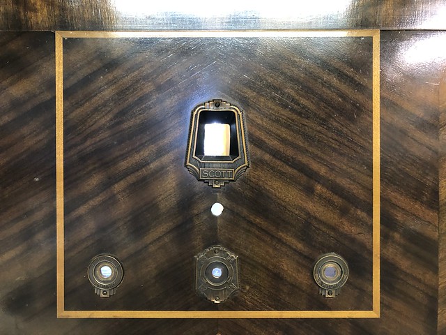
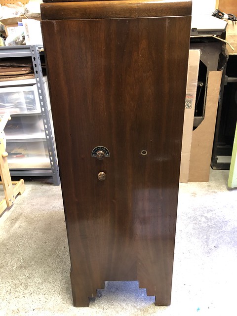
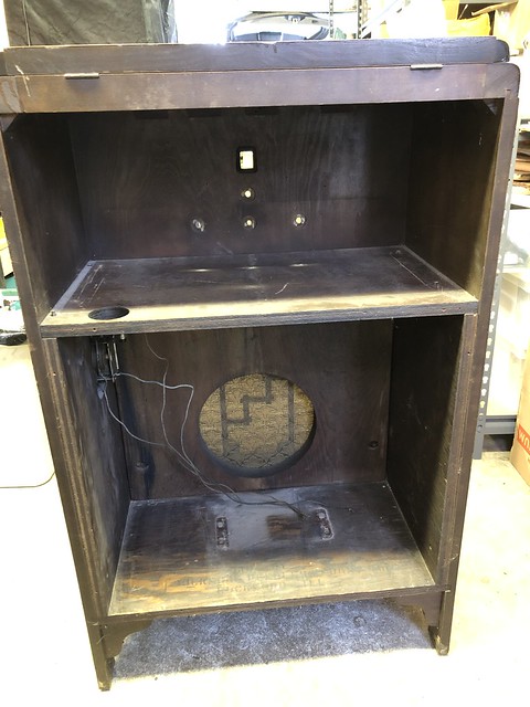
The radio came installed in a "Lido" cabinet:
The inside of the cabinet appears to say: "Made By Rockford Peerless Furniture Co, Rockford Ill":
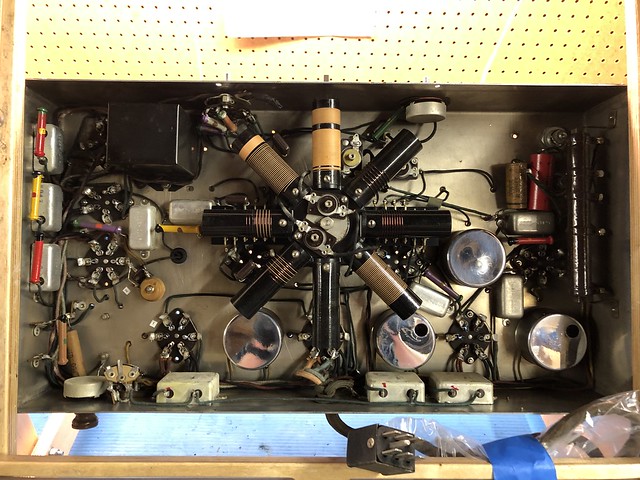
Main Chassis
Photos of the radio itself:
From what I've read this chassis is the later model and should have the tuning meter - but mine doesn't have one. I assume that's a modification?
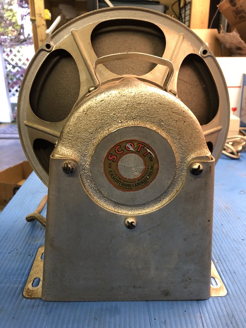
Speaker
Power / Amp Chassis
The previous owner used 2A5 -> 45 adapters. I've got some actual 45 tubes to put there.
Miscellaneous
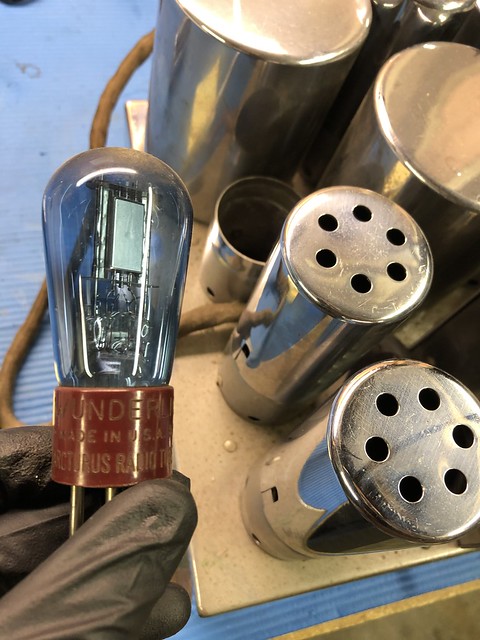
This is a shortwave addon?
Replies to This Discussion
-
So that is a late AW12 Deluxe, built sometime in 1934. I can't narrow it down much more than that, but since the AW15 appeared mid-year, maybe the first half of '34...
-
That is a very nice set. The Lido cabinet is probably a little more scarce than the Napier, and almost as nice, so it is a great cabinet to have. Your set looks to be in very nice condition, all original. Yes...put 45s back in the amp!
The pre-tuner in the cabinet can be used on all wavebands, it helps provide some additional selectivity around strong stations. These units are found with almost all the 12 Deluxe sets in this period. The Wunderlich tube will almost certainly be good if it has filament...they hardly ever go bad. They are tough to replace, but you can make a substitute from a 55 and a piece of wire.
Before powering the set, go over everything and check the power supply carefully. You will have a wonderful, enjoyable set once you get it playing!
Kent
-
Very nice example- both the radio and the Ledo Cabinet (with the original speaker cloth). There is a copy of the Instruction Manual in the Scott Info Archive above - then select Set folders, open the AW-12 folder to find several AW-12 set items including an Owners Manual of 15 pages or so.
Rockford Peerless Furniture made many of the 1930's era Scott cabinets. Yours is the early version Ledo with the darker Circassian Walnut veneers on the front, correct for the AW-12 you have.
The cabinet mounted Short Wave Antenna Tuner acts to peak the antenna resonance and will really bring in a SW station. As you tune the radio on SW, you can turn that tuning knob too to maintain maximum sensitivity.
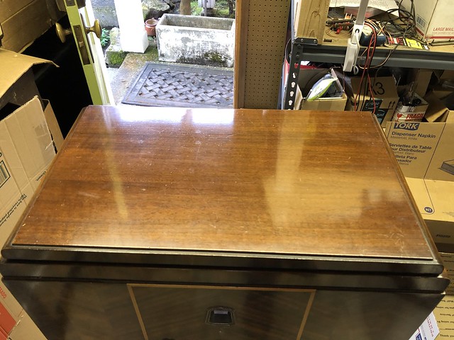
The visual tuning meter stalk also supports the dial light, such that it also projects the tuning meter needle shadow onto the dial strip. Looking at your top view photo, I think I see your small tuning meter.
To clean the chrome, remove much of the dust and dirt with a smaller artist brush and vacuum cleaner. Then I like Turtle brand liquid chrome polish and a few small squares of old towel as applicators. I recall a cap to replace inside of each IF can across the back of the receiver - you will need to unsolder the metal braid of the grid cap wires and remove the grid cap too in order to remove the chromed coil covers, which is a good time to detail the chrome in the hard to reach places.
If yours is a really late version AW-12 (Deluxe with AVC) instead of using 5 of the 6 pins of the big Jones plug, the last version uses all 6 pins and a revised audio pathto the amp (is what I have).
-Good luck on your restoration. Restored electrically, it is a great radio. Yes, use 45s not 2A3s.
-
Nathan, for a good restoration orientation, find this thread from January 2019 on this Scott site:
ELECTRICAL RESTORATION: ALL WAVE 12 DELUXE
by Jon Ketron.
-
Thank you both for the fascinating details on this set! And also the great pointers for restoration.
I plan to add more pictures as I go through the restoration.
-
I'm finally now beginning the restoration of the Allwave Deluxe.
David - that Turtle chrome polish is great stuff. I ordered a bottle and spent some time getting the dust and dirt off and everything polished.
There are still a couple of rust spots that I couldn't buff out - I plan to use Evaporust Gel on those since that's pretty gentle (although it takes some time to remove rust).
Next I took off the dial to get a closer look at where the tuning meter should be:
It looks like the meter was previously removed as I also found the snipped leads under the chassis (top left in the below picture). Weird that someone would go through the trouble to remove the meter even if it didn't work.
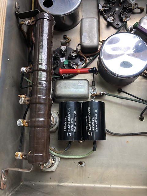
So far I've been carefully going through the Riders schematic and identifying components. The only thing I've replaced so far are the electrolytics with 8.2uF / 630V film caps.
-
Until you locate a tuning meter, be sure to connect the "sniped leads" together. The tuning meter is in series with the B+ line to the plate of the Wunderlich tube. See circuit diagram.
My AW-12 has a 2 lug terminal strip mounted on left end of the right tuning capacitor cover, just above the shaft to the dial mechanism. You may find the threaded hole there, used to secure the terminal strip. Scott's instructions with a faulty tuning meter is to disconnect the meter from the terminal strip and bridge the terminal screws with a short wire to allow the radio to function normally. (later models AW-15 & AW-23 have a different circuit for the tuning meter not in a B+ circuit.)
Do replace (or rebuild) the various metal bathtub caps, but leave them in place for appearance sake. However, the 3 large ones across the back apron of the chassis have coil inside along with the cap and being in a low voltage grid circuit are usually left alone.
Do replace the paper cap in each of the IF coils before you re-install the chrome plated covers.
If removing the coil wheel, critical to first turn the band switch to broadcast band (extreme counter clockwise - about 7 o'clock position for the band pointer knob). And do not turn the band switch until you re-mount the coil wheel. Otherwise, you risk breaking the contact switch located in the antenna coil can above the gear drive that turns the coil wheel. Watch for the two spring loaded capsules that serve as detents for the 4 bands. (Stinkers to replace if a spring or bullet shaped cover is lost.) IF you have already removed the coil wheel in the improper position, seek advice here before remounting the coil wheel.
-
Thanks for your advice David!
I've made some good progress on the electrical restoration.
Power / Amp Chassis
- Electrolytics replaced with 10uF 630V film caps
- 1/2uF bathtub cap and 2uF (I think) cubical cap replaced
- Frayed power cord replaced
- Original fuse was damaged - bypassed for the moment, new 3A fuse on order
- One 100K resistor measured 140K so made a reproduction dogbone for it (paint still drying - haven't installed it yet). The rest of the resistors in the set measured within spec.
Tested all tubes on the TV-7 - all were good, tested Wunderlicht tube for filament continuity (good). Added real 45 tubes. At this point all of the electrolytics had been replaced so I connected an antenna and brought it up on the variac. And it played! All three bands are working.
Main Chassis
- 0.025uF tubular caps in IF cans and the one below chassis restuffed (brown hot glue used to reseal)
- Next I replaced the rest of the bathtub caps. I didn't want to do anythin that wouldn't be reversible so I used small terminal strips soldered to a corresponding bathtub cap terminal to mount it.
-
A few questions:
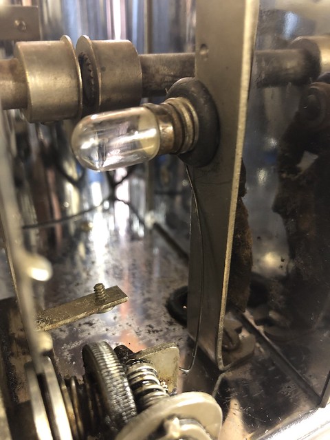
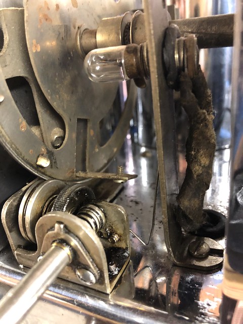
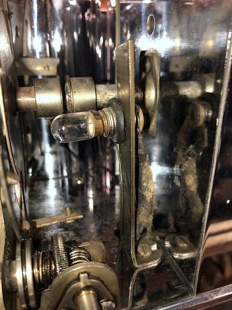
Do you know the correct lamp type for the dial? The one that it came with seems quite dim for the job.
This length of springy wire seems like it's used to secure the lamp?
I couldn't find any threaded hole where the terminal strip would mount - although I have seen pictures online of other sets so I think that I understand what you're talking about.
Is it possible that this set just had the meter hard wired? How much variation is there between these sets and how they're assembled?
How custom were they? Is it possible it didn't have a meter to begin with (an option)?
Thanks again for your help.
-
Hi Nathan,
just a few observations,
the wire that olds your dial lamp is what remains of the tuning dial pointer, looks like a spring wire an inverted L in shape,
it goes between the bulb and the dial to throw a shadow across the middle, a length of piano wire will work.
your bulb looks a little dim, make sure that it's a 2.5v type, a #41 should be ok
Mike
-
Nathan;
have a look at john ketrons photo's restoring an allwave fifteen, in the photo's section on this site, photo#61 shows the dial with lamp tuning meter and scale, yours will be very similar.
Mike
-
Thanks Mike - that makes a lot more sense. :)
The photo makes it much clearer.
© 2026 Created by Kent King.
Powered by
![]()

